Close Air Support (CAS) / Forward Air Control (FAC)
United States | 1976
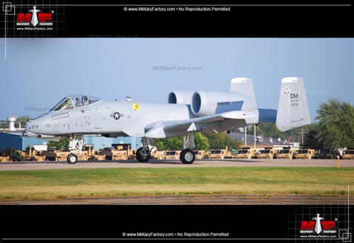
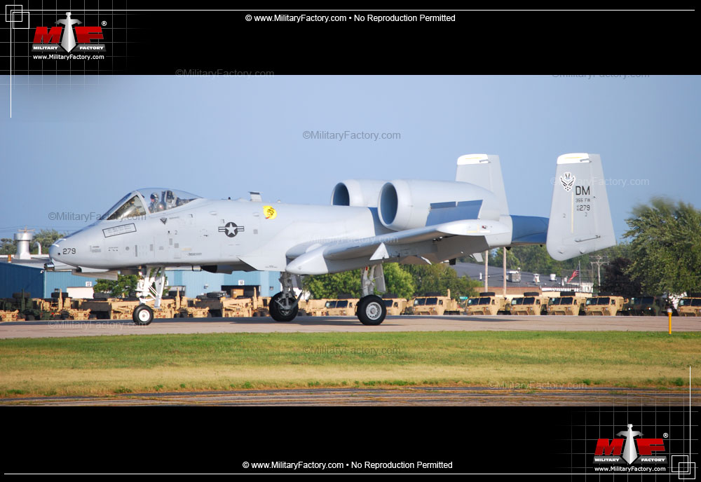
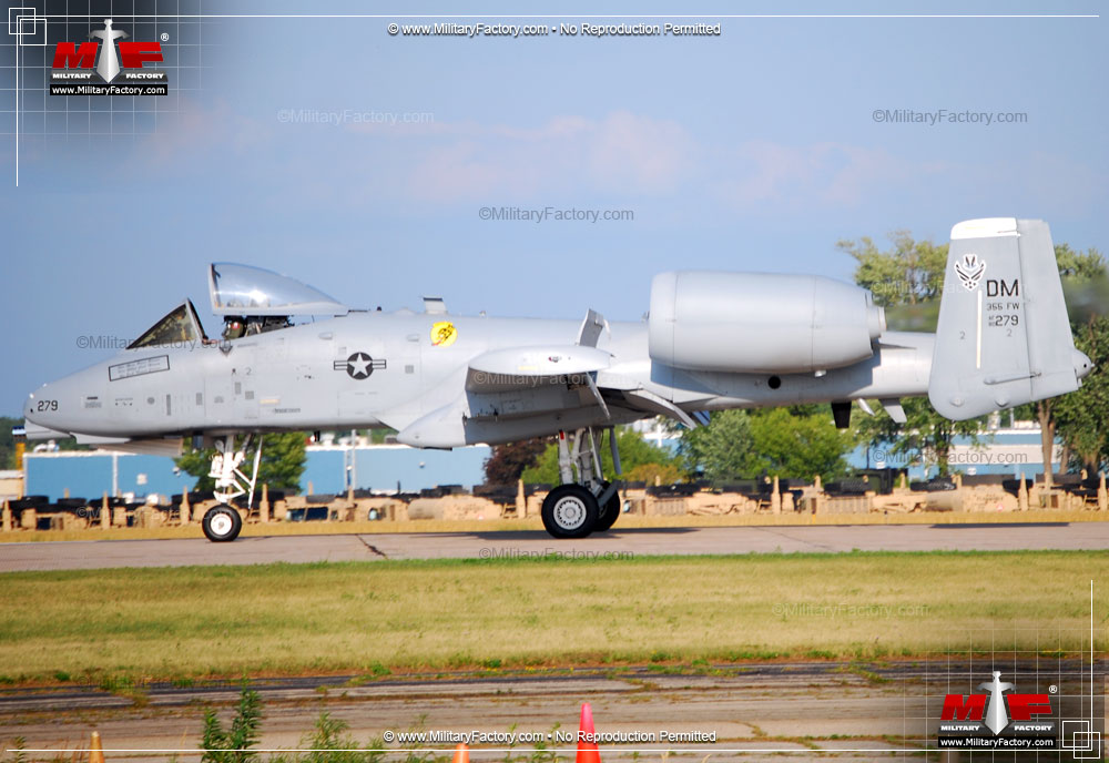
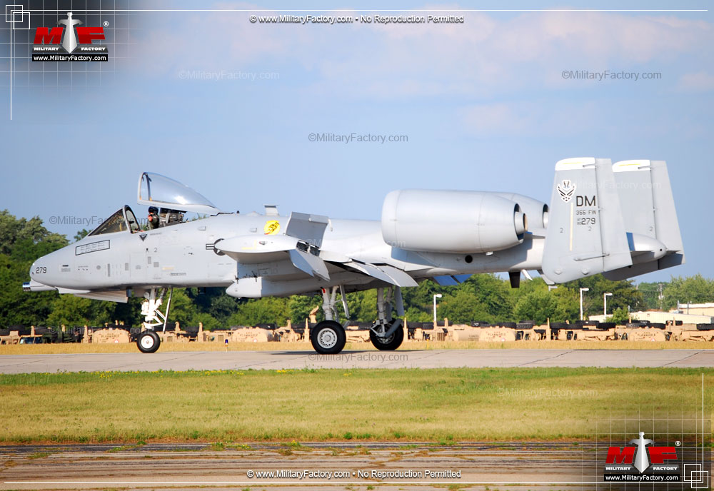
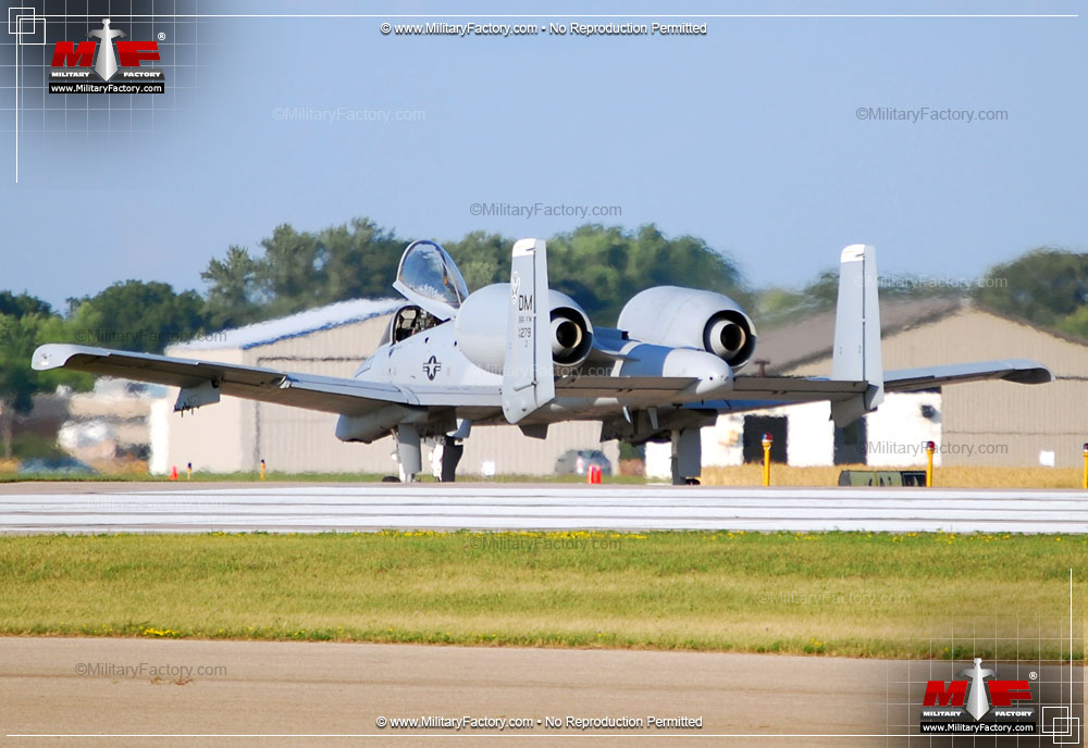
"The Fairchild Republic A-10 Thunderbolt II, developed specifically for the Close-Air Support role, has become a legend in the military aviation world."
Power & Performance Those special qualities that separate one aircraft design from another. Performance specifications presented assume optimal operating conditions for the Fairchild Republic A-10A Thunderbolt II (Warthog) Close Air Support (CAS) / Forward Air Control (FAC).
2 x General Electric TF34-GE-100 non-afterburning turbofan engines developing 9,065 lb of thrust each. Propulsion
439 mph 707 kph | 382 kts Max Speed
34,695 ft 10,575 m | 7 miles Service Ceiling
474 miles 763 km | 412 nm Operational Range
6,000 ft/min 1,829 m/min Rate-of-Climb
Structure The nose-to-tail, wingtip-to-wingtip physical qualities of the Fairchild Republic A-10A Thunderbolt II (Warthog) Close Air Support (CAS) / Forward Air Control (FAC).
1 (MANNED) Crew
53.3 ft 16.25 m O/A Length
57.5 ft (17.53 m) O/A Width
14.7 ft (4.47 m) O/A Height
27,999 lb (12,700 kg) Empty Weight
51,998 lb (23,586 kg) MTOW
Armament Available supported armament and special-mission equipment featured in the design of the Fairchild Republic A-10 Thunderbolt II (Warthog) Close Air Support (CAS) / Forward Air Control (FAC) provided across 11 hardpoints.
STANDARD, FIXED:
1 x 30mm General Electric GAU-8/A seven-Barrel Gatling Gun mounted under the nose.
OPTIONAL:
Up to 16,000 pounds (7,200 kilograms) of mixed ordnance across eleven underwing and underfuselage pylon stations, including:
Variants Notable series variants as part of the Fairchild Republic A-10 Thunderbolt II (Warthog) family line.
YA-10 - Initial Prototype Model Designation; two examples produced.
YA-10A - Pre-Production Model Designation of which six were completed for evaluation.
A-10A - Base Production Model; dedicated Close-Air Support (CAS); single-seat.
YA-10B - Proposed Two-Seat Prototype; all-weather/night-attack weapons platform; single example produced.
A-10C - Upgraded/Improved A-10 system; made operational in September of 2007; modernized "glass" digital cockpit; improved datalink function; improved weapons management system.
OA-10A - Observation Variant Model / Dedicated Forward Air Control (FAC); single-seat; based on A-10A production models and identical to them in both structure and appearance.
The A-10 Thunderbolt II was designed exclusively to fulfill the Close-Air Support (CAS) role from the outset, perhaps matched only in scope by the Soviet/Russian Sukhoi Su-25 "Frogfoot". The terminology inherent in "Close-Air Support" was generally defined in a variety of ways by each respective nation (and perhaps further viewed differently by even individual commanders). The Vietnam War showcased such a need for the United States Air Force, where their thirsty, high-flying jets could do little in the way of directly supporting troops in contact with the enemy by roaming on station until called and then heading in to deliver payloads with pinpoint accuracy. Additionally, these aircraft held little in the way of dealing directly with heavy armor systems, their 20mm Vulcan cannons useful in engaging other aircraft and perhaps even light-skinned vehicles. Helicopter gunships provided some solution to the problem but no true dedicated systems existed - apart from say the prop-driven Douglas A-1 Skyraider. An answer was needed and that answer would become the Fairchild Republic A-10 tank-killing "Warthog".
The Tank Buster in World War 2
Tank busting elements played a crucial role in World War 2 where tank-on-tank battles often times moved the war in one direction of the other. As such, all sides delved into the development of aircraft with suitable armament to deal with enemy armor. Perhaps the best known of these became the Junkers Ju 87 Stuka, armed with two underwing cannons pods with the projectile velocity to penetrate the armor of Soviet tanks. This exercise no doubt showcased the value of a dedicated tank busting system but even in the years after the war, no party put forth a capable design, feeling other systems were more than efficient at the CAS role.
The "Warthog" Name
Though officially designated "Thunderbolt II" in April of 1978 in honor of the other exceptional Republic product - the P-47 Thunderbolt of World War 2 fame - the A-10 carried the company tradition of having been given an unofficial name in line with the "hog" reference. The Republic F-84 became the first to use this moniker, being nicknamed "Groundhog" or "Hog" while the F-84F Thunderstreak became the "Superhog" and the Vietnam-era F-105 Thunderchief became the "Ultra Hog". In staying with this tradition, the A-10 Thunderbolt II had unofficially become known as the "Warthog" over the years, due to its less-than-beautiful outward appearance. The name was dropped in a speech given by Major Michael G. Major at the Tactical Air Warfare Center (TAWC) Review. The name stuck with crews but has since evolved to the simpler "Hog" or, perhaps more appropriately, "Hawg". At any rate, the Thunderbolt II official designation and Warthog unofficial nickname are essentially interchangeable when talking about this fine aircraft.
Close-Air Support (CAS)
Close-Air Support (CAS) functions relied on some distinct requirements that would differentiate the design from existing strike fighters. This aircraft could have to operate in the thick of combat actions and become the target of small arms, large caliber ground-based cannons and missile batteries. As such, survival was of the utmost importance for both pilot and machine. The pilot would have to sit in a reasonably armored environment and the aircraft's critical internal operating components (hydraulics, avionics and fuel) would also have to be designed in such a way as to keep the aircraft aloft even after sustaining combat damage that would do in most any other airplane. As a system charged with attacking both heavily armored and lightly (or unarmored) ground targets, the aircraft would have to heavily armed and capable of an impressive payload output. Additionally, as a CAS aircraft, the new design would have to make use of efficient engine power while not expending vital fuel stores, providing the capability of loitering in a target area for hours until called to action by ground forces or command.
The USAF Need
To this point, the USAF had nothing but the so-called "hotrods" in its stable by the time of the Vietnam War. These aircraft, mostly jet-powered, could undoubtedly fly the hairs off of a tick but, in terms of CAS requirements, that also equaled minute-long loitering times and an excessively long turning radius. This type of hyper performance allowed for perhaps one or two passes on a target before having to return home to rearm and refuel. These aircraft were also notorious for long take-off and landing rolls meaning that they required a firm, large area from which to operate from. There was also the issue of inherent complexities in the refueling and rearmament process and limitations to payload capabilities, all pointing to the dire need for a true dedicated CAS aircraft. The propeller-driven Douglas A-1 Skyraiders of the war proved the validity of low-level, close-support aircraft with exceptional firepower, robust qualities and agility at low speeds/low-altitudes but what she lacked was the performance of her mighty jet-powered counterparts.
Republic Becomes Fairchild Republic
Republic Aviation got its start in 1939 after the Seversky Aircraft Corporation ran into financial issues and was reformed un the new Republic name. The new firm, operating out of Farmingdale, New York, was finally able to make something of a marketing and financial splash with their excellent P-47 "Thunderbolt" in June of 1942. The P-47 - known as the "Jug" - was an eight-machine-gun-armed beast that proved suitable in both the fighter role as well as the ground strike role. She went on to be produced more than any other American fighter in World War 2 and made Republic a household name. The Thunderbolt saw extensive use in both Europe and the Pacific and was generally liked by her pilots, though oft-overlooked by most students of the war today, preferring instead to focus on the more sexy P-51 Mustang, Fw 190 or the Supermarine Spitfire. Interestingly, American military use of the P-47 ceased immediately after the war and no plans were made to bring them out of storage by the time of the Korean War. Many supporters of the Jug believed that the hard-hitting qualities of the P-47 in that conflict would have made a difference.
Nevertheless, the post-war world was the jet's age of enlightenment. Naturally, Republic jumped into the fray and developed the single-engine F-84 fighter series that encompassed the straight-winged F-84D "Thunderjet", its swept-wing cousin the F-84F "Thunderstreak" and the dedicated reconnaissance platform the RF-84F "Thunderflash". Thunderjets proved valuable in the Korean War and many served up until the early 1970s with Air National Guard units before reaching their inherent usefulness.
Next on the Republic drawing boards proved to be the large and complex, but ultimately dominant, F-105 Thunderchief. This single-engined monster became the largest USAF-serving fighter to date and saw extensive service in the Vietnam War, undertaking a variety of roles including strike and reconnaissance sorties. She served primarily in the ground attack role until replaced by the excellent multi-role, twin-engine, two-seat McDonnell Douglas F-4 Phantom II. Of the 833 Thunderchief systems delivered, 397 of these would be lost to action in the skies over Vietnam.
Republic attempted several forays into the civilian and passenger airliner markets but failed on to generate much interest let alone revenue. The company fell on hard times and a last-ditch effort to sell the USAF on an attack aircraft had failed. Republic Aviation was acquired in full by Fairchild in July of 1965.
Fairchild began as the Fairchild Aviation Corporation in 1929 and became Fairchild Hiller in 1964 after the purchase of Hiller Aircraft. They then became Fairchild Industries in 1971 following the death of founder Sherman Fairchild. The A-10 Thunderbolt II would be marketed under the joint Fairchild Republic name. Beyond the A-10, Fairchild continued to evolve and was renamed Fairchild Dornier after taking over the civilian side of the German aircraft company in 1996. Today, Fairchild has been absorbed by the German insurer Allianz A.G., along with the American company, Clayton, Dubilier & Rice, Incorporated, and operates under the M7 Aerospace branding.
The AX Competition
The AX ("Attack Experimental") program began in June of 1966 with a detailed requirement put together in September of that year. On March 6th, 1967, the USAF put forth a Request for Information (RFI) to no fewer than twenty-one trusted defense contractors. Follow-on study contracts were then awarded to General Dynamics, Grumman, Northrop and McDonnell on May 2nd of 1967 in an effort to find the best arrangement of protective armor, internal systems and fuel on a new design centering on survivability and firepower. The program's high-reaching goal was to develop a highly-sustainable dedicated CAS aircraft to fulfill the need so painfully unveiled in the Vietnam War. Should full-scale war develop in Europe through a Soviet land invasion involving tanks, infantry and support vehicles, NATO would need to respond to such force with equal force itself - dealing with targets in the thick of night or in the adverse weather conditions so common throughout the European mainland. The new aircraft would replace the outmoded Douglas A-1 Skyraider in the role for the USAF. It was thought best that the new aircraft should make use of two turbofan engines to remove the need (and required area) for the operation of spinning propeller blades as well as allow for operations on a single engine if need be. Responses were delivered from Boeing, Cessna, Fairchild Republic, General Dynamics, Lockheed and Northrop on August 10th, 1970.
An additional requirement in the AX competition called for the aircraft to be armed with a massive rotary 30mm cannon, one of the largest production armaments to ever be fitted in a combat aircraft. The 20mm M61 Vulcan cannons of the Vietnam War-era aircraft proved sufficiently enough against other air targets but it was woefully insufficient to combat armored targets of value. Combat experience, even those recorded as far back as World War 2, shown a need for a large caliber repeating weapon to affect enemy armor at range and from the air.
Two companies were selected as the early winners, this being Northrop and Fairchild Republic. Each company was granted design, development and construction of two prototype aircraft to be designated as the YA-9A and the YA-10A respectively. For Republic, it was a shot in the arm, their assembly lines now running cold since production had ended on the F-105 Thunderchief.
The Northrop YA-9
The Northrop submission was quite conventional at its core, appearing in some ways like the Sukhoi Su-25 "Frogfoot" combat platform with its straight-winged, multi-hardpoint design running along a slender semi-monocoque fuselage with a riveted stressed aluminum skin. The cockpit was held well-forward in the design, offering up good forward and side views out over the short nose assembly. Wings were shoulder-mounted and fitted amidships, with clipped wingtips. Wing surface area was large to promote additional drag as well as offer up ten strong underwing hardpoints for varying ordnance loads. Engines were fitted to the lower portion of the central fuselage and held some distance apart from one another for survivability . The empennage was traditional and tapered off into a large-area, single vertical tail fin sporting two upward-angled stabilizers. When at rest, she sat low to the ground on a conventional tricycle undercarriage, all with single wheels. The undercarriage was made up of two main landing gear legs retracting into each engine assembly side and a nose landing gear leg retracting under the cockpit floor. The nose leg was offset to the portside to make room for the intended 30mm nose cannon, though an 20mm M61 Vulcan was fitted in the interim. Fuel tanks were fitted inside of each wing assembly outboard of the engine placement. Flight controls were made redundant to promote survivability from direct hits. The pilot sat in an armored "tub" made of aluminum, though production aircraft would feature titanium. Engines were a pair of developmental Lycoming YF102 series turbofans.
What made the YA-9 most unique was the inclusion of the Side-Force Control (SFC) system that integrated movements of the speedbrakes with the rudder to prevent "slideslip". This helped the pilot to maintain the proper angles on a target without banking the aircraft to the extreme, only to have to realign his aim once again. This feature was made optional to the pilot, to be used as he saw necessary, but was thought to grant the YA-9 a heightened form of accuracy in munitions delivery.
In practice, the YA-9 prototypes flew well, totaling some 146 hours through 92 flights. Her first flight was on May 30th, 1972, twenty days after the YA-10, with Lew Nelson at the controls. Handling characteristics were found to be better than that of the competition, with less roll inertia, and the SFC system itself proved a success.
The YA-10
The YA-10, on the other hand, was a different sort of creation. Its unorthodox design immediately made it stand out from the competition. She handled well when going airborne for the first time on May 10th, 1972 out of Edwards Air Force Base (AFB) with Howard "Sam" Nelson (unrelated to Northrop's Lew Nelson) at the controls. The second flight ended with some flat tires but nothing serious. The YA-10 fitted its engines high on the fuselage, away from ground fire and debris typical of unprepared runways. The wings were large and straight formed, encouraging drag and low-speed, low-level flight with split airbrakes fitted to each wing trailing edge. Like the YA-9, the YA-10 gave its pilot an excellent view from his seat. Internally, the YA-10 also featured redundancy in controls and subsystems. The second YA-10 went airborne on July 21st, 1972.
The USAF looked at each aircraft closely, with evaluation of the systems proceeding concurrently from October 10th, 1972 to December 9th, 1972. While both airframes exceeded the USAF expectation, the Republic YA-10 evaluation slightly outmatched the Northrop submission on a variety of fronts. The YA-10 was a more structurally "ready" pre-production aircraft than the prototype form offered by Northrop, potentially allowing for quicker full-scale production once development commenced. Pilots generally believed in the unique layout of the YA-10 and its inherent survivability qualities when compared to the conventional Northrop submission. The low-set wings of the YA-10 was also noted for its promotion of quick rearming. This was in contract to the high-mounted wings on the YA-9. The Republic design was also slated to make use of the existing TF34 turbofan engine series already in use by the USAF and the USN. As such, there would be little in the way of engine development to slow the program down.
Winner Announced
Like most any multi-million dollar deal regarding the American military, these competitions are almost always decided on the political front. The Republic firm was going through some tough times and they represented the relatively small aeronautical presence in the state of New York along with Grumman. Southern California, where Northrop was based, had long held a strong position in the aviation industry. It would seem that Republic and the state of New York could use the AX contract to keep constituents happy.
With all the results in, and all factors accounted for, the USAF announced Fairchild Republic as the winner of the AX program on January 18th, 1973. The contract amounted to $159,279,888 and called for ten YA-10A developmental models plus two additional airframes. An option was included for 48 first-run production aircraft after the development of the GAU-8/A 30mm cannon was completed. General Electric received $27,666,900 for the development of a slightly modified TF34 engine that could be made interchangeable on the new YA-10 regardless of whatever fuselage side it was mounted to. The production contract was signed on March 1st, 1973.
On the losing front, the Northrop YA-9 prototypes were sent to NASA in the hopes they could be of some use to the space industry. The space agency never found a home for the YA-9s and sent them to the museums at Edwards AFB and March Field to be kept as showpieces.
Not a Done Deal
Despite the announcement, the USAF still needed to prove the expensive requirement for a dedicated CAS aircraft to its detractors. Every major program, considering the amount of money involved, always faced an uphill battle even along the political front. The YA-10 proved no exception and felt the heat from a congressional Texas delegation bent on drumming up more business for their closing Vought A-7 Corsair production lines. The members argued that a modified A-7D model, this projected with a long fuselage housing the new GE 30mm cannon, could more effectively fulfill the CAS role than the all-new - and inherently expensive - YA-10. The US congress recommended a fly-off between the Corsair and the Thunderbolt but the USAF was slow to respond. When the congress cut funding to four preproduction YA-10As, the USAF finally jumped to action and commenced with the competition. The fly-off occurred from April 16th to May 10th, 1974 and the results were encouraging to the Republic product, showing their ugly aircraft to be the superior breed in the CAS aircraft class. The YA-10 was able to loiter in a designated target area for up to two hours against the A-7Ds menial 11 minutes of flight time. Consideration for the A-7 as a CAS aircraft was dropped and the YA-10 lived to fight another day.
The first prototype YA-10 was put in "flyable" storage on April 15th, 1975 - her work now complete. Her resume included 467 flights totaling nearly 510 hours of flight time. The second prototype soon followed suit and was placed in storage on June 13th, 1975 after amassing 354 flights totaling nearly 549 hours of flight time. Six preproduction aircraft would soon take their places beginning in February of 1975 with each one charged a different program goal. The sixth preproduction example was later lost to a double engine flame out on June 8th, 1978, the pilot ejecting safely with his Douglas ESCAPAC ejection seat. Despite testing moving along rather comfortably, the lack of further preproduction examples inevitably led to program delays. A further delay occurred after test pilot Sam Nelson was tragically killed while conducting a series of low-level loops at the 1977 Paris Air Salon at Le Bourget. Otherwise, Thunderbolt testing revealed little in the way of major flaws in the unorthodox design.
The 6510th Test Wing of the Air Force Flight Test Center out of Edwards AFB and the 3246th Test Wing at Elgin AFB were two of the earliest recipients of the prototype and preproduction YA-10 examples. These groups became the first such USAF entities to handle the aircraft. The 3246th was of particular note for they handled the required armament trials.
A-10 Production
Republic production facilities were not on par with the latest offerings found in her defense competitors. Luckily, the A-10 was not a highly-advanced aircraft requiring the latest in technologies to put her together. However, the USAF expressed concerns about the delays in production and ordered Republic facilities to be brought up to speed at the company's expense. This was done to the USAF's pleasure but hurt Republic's bottom line in the process. Production aircraft were very similar to the preproduction forms with a few slight exceptions. Ventral strakes were added and leading edge slats were now fixed. The wingspan was increased out some 30-inches while the flap angle was adjusted. A laser receiver for the the AN/AAS-35(V) PAVE PENNY was added to the right side of the forward fuselage to be used in conjunction with laser-guided munitions (PAVE PENNY searches for the reflected laser light applied to a target by other ground-based "friendlies"). While preproduction aircraft were fitted with the Douglas ESCAPAC ejection seat system, production models utilized the McDonnell ACES II series.
Final assembly of production A-10s was moved to Hagerstown, Maryland. The first production A-10A achieved flight on October 10th, 1975. Delivery was delayed some five months before the 355th TFW received their first A-10As in March of 1976, ironically replacing their outgoing Vought A-7 Corsair IIs. The 355th carried out the required test and evaluation of the A-10A and took part in the 1977 Joint Air Weapons System (JAWS) trials. These trials would prove crucial in developing the tactics and defining the true battlefield role of the new A-10A once in operational service and its relation to the existing battlefield components such as artillery and attack helicopters - the latter essentially sharing the same tank-killing role as the A-10. The first operational A-10 squadron appeared in October of 1977 as the 333rd Tactical Fighter Training Squadron (the "Lancers") and they were soon joined by the 358th TFTS "Lobos". The 354th Tactical Fighter Wing out of Myrtle Beach produced the 353rd, 355th and the 356th Tactical Fighter Squadrons. The designation of "Thunderbolt II" was officially assigned by the Pentagon on April 3rd, 1978, in a ceremony commemorating the 100th production A-10 airframe. The final A-10 was delivered to the USAF in 1984.
The 81st Tactical Fighter Wing based out of England took delivery of their A-10As after the trials and evaluations were completed. Since the battlefield was undoubtedly to be European in nature, this fighter wing became one of the important early operators of the new aircraft. The first A-10A arrived on January 26th, 1979, and ultimately was fielded by no less than six squadrons - the 78th, 91st, 92nd, 509th, 510th and the 511th Tactical Fighter Wings. From their bases in England, the A-10A could be deployed to six awaiting Forward Operating Locations (FOLs) across West Germany. The 81st was eventually branched off in 1988 to form the 10th TFW based out of RAF Alconbury.
Five Air National Guard (ANG) state-side squadrons were set up to help reinforce the 81st stationed in Europe in the event of total war. These became the 103rd TFS out of Connecticut, the 104th TFS out of Massachusetts, the 128th TFS out of Wisconsin, the 174th TFS out of New York state and the 175th TFS out of Maryland. The 103rd was the first to receive their A-10As beginning in May of 1979.
The Air Force Reserves were the next recipients for the A-10A. The 917th TFW took delivery of their examples in October of 1980. They were joined by the 442nd TFW, the 926th TFW and the 930th TFW. Other groups soon followed and included the 23rd TFW out of England AFB in Louisiana as well as the 51st Composite based in South Korea and the and 343rd Composite based in Alaska. The latter two groups took delivery of their systems from 1981 into 1982.
A-10 Walk-Around
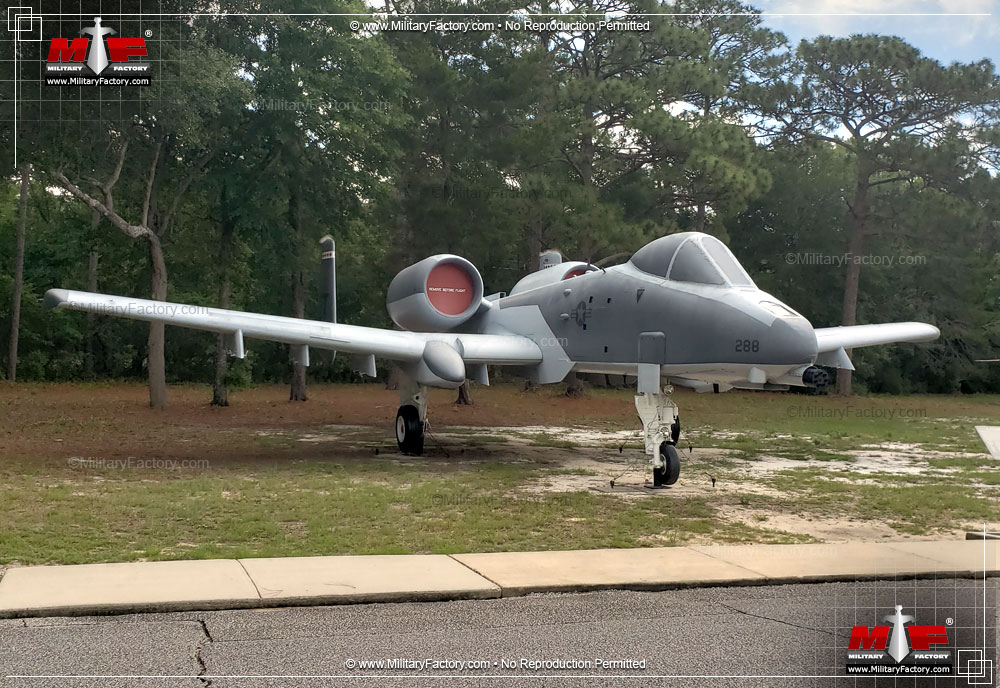
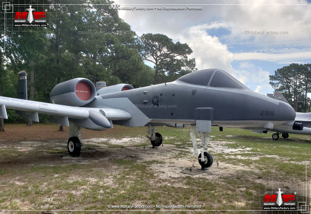
Externally, the A-10's appearance became its defining characteristic. No other aircraft had ever taken on its seemingly unorthodox layout and no other aircraft has since copied its success. Since the role dictated the design, the A-10 made use of several key layout features that defined her legacy. Her fuselage was of a slender shape with a short nose assembly, slab sides and tapering downwards to the empennage. The underside of the fuselage was well-flat from nose to tail. Electrical equipment was fitted to the rear of the cockpit while the 30mm cannon and applicable ammunition drum took up most of the forward fuselage with the cockpit and forward landing gear. The left main and right main fuel tanks were situated in tandem just aft of the electrical equipment area with the right main tank coming first in the layout and the left following. Many of the internal systems of the A-10 were made readily accessible by way of large hinged access panels. These panels dotted the fuselage to help make maintenance and repair a somewhat easier process when compared to other aircraft.
The A-10 Cockpit
The cockpit was held well-forward in the design and sported a two-piece raise canopy to allow the pilot excellent views forward and to the sides of his/her aircraft. It was set ahead of the wings and even offered views to the ordnance loads to be held under each wing assembly while offering a limited glance to each engine mounted further aft - useful in battle damage assessment. The pilot sat in a raised position in a relatively spacious cockpit. His ejection system was the high-backed ACES II series ejection seat. The rear portion of the canopy was hinged at the base and powered. The forward canopy was divided by framing and sat over a HUD (Heads-Up Display) system atop the instrument panel. The forward canopy could resist blows from a 20mm cannon. To each side of the HUD were the accelerometer (on the left vertical frame post) and a standby compass (on the right vertical frame post). The rest of the canopy glass was bulletproof to an extent. The instrument panel itself was well-organized and in many ways reflected Republic's experience in the development and production of their jets sometime before. The throttle was set low and to the left of the pilot's leg while the control stick was situated conventionally between the pilot's legs. Interestingly, the Warthogs initially featured no autopilot function, requiring the operator to maintain complete situational awareness on the longest of flights. This was thankfully rectified by way of a modernization program some time later.
One of the most noteworthy design elements of the cockpit was its situation within a titanium armored "tub". Despite its name, the "tub" was actually nothing more than titanium slabs bolted together as opposed to a single forged unit. The tub offered protection from 23mm projectiles from below, the front, sides and rear. Only the rear titanium panel held openings for hydraulic, electrical and other control systems.
The A-10 Instrument Panel
The instrument panel appeared quite conventional by modern standards. The center was dominated by the traditional attitude director indicator and horizontal situation indicators. Just above those and offset slightly to the left was the radar warning system that alerted the pilot to radar tracking, targeting and engagement by enemy systems. The azimuth direction scope indicator was to the left of the warning system. All weapons controls were congregated into an easy-to-reach panel subset spaced to the lower left, just above and ahead of the pilot's left kneecap. Each underwing pylon could be controlled from this collection of switches and the pilot could further keep track of the 30mm rounds available to the nose cannon via a simple counter. Later A-10s fitted a slightly revised armament panel to incorporate use of the self-defense AIM-9 Sidewinder air-to-air missile capability. Armament controls were extended to the throttle and control stick as well. Undercarriage functions were accessed along the lower left. Additional flight controls were seated along the upper left of the forward instrument panel. The lower right of the panel contained all engine controls and applicable function gauges including the fuel indicator. Above this collection was the Maverick missile television screen. This served to target and guide the Maverick air-to-surface missiles through pinpoint accuracy. Of note in the cockpit were the three yellow-and-black "FIRE PULL" handles running across the top of the instrument panel. Each controlled different onboard fire extinguishers and could be pulled by the pilot in the event of a fire. The left and right handles controlled the extinguishers for each respective engine. The center handle offered extinguishing aid to the Auxiliary Power Unit (APU) when needed. The instrument panel could be further accessed (by technicians) in that it hinged forward to allow for easier access. The center console ran ahead and between the pilot's legs, this area holding the Laser Spot Seeker Panel and the Essential Circuit Breaker Panel. The left console was afforded an area to collect the "piddle packs" of urine, made available for the A-10 pilot to relieve himself with on long flights.
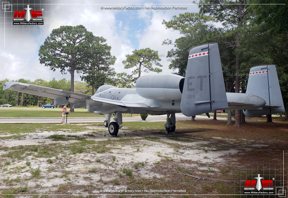
The Mainplanes
The wing mainplanes were low-mounted and set amidships. Their low orientation meant that they was relatively easy for munitions specialists to access the many pylons during the armament and reloading phases of a mission - an edge that the prototype A-10 maintained over the Northrop submission. Each wing was such that it incorporated no less than three strong main spars and held two large internal fuel tanks (one port and one starboard, fitted near the wing roots). The wings were straight in design, offering no sweep along either the leading or trailing edges. Her tips were also clipped and gave her a unique look among the hotrod jet fighter designs surrounding her. The wings each held two sets of flaps along the trailing edges, inboard and outboard of each wheel sponson. The aileron doubled as the split speedbrake and was set along the outermost trailing edge area. The speedbrake split open in two halfs, with one half of the unit opening upwards and the other half opening downwards, providing the necessary low speed functions of the A-10 at low altitudes. The trim tab was allotted to the upper speedbrake panel assembly. There was a single point refueling access system located at the forward end of the port wing wheel sponson. This unit was accessed via a handy flip-down door and held all controls for refueling and defueling the aircraft. All fuel was concentrated along the mass of the aircraft, near its center of gravity, ensuring that changes in the internal fuel load would have as little effect as possible on the aircraft's performance.
The Undercarriage
Of note was the semi-recessed function of the main landing gear legs. These were set up in a conventional tricycle arrangement. The semi-recessed approach for the main landing gear legs was used so as not to break up the internal wing structure as encountered when using a conventional wheel well. The semi-recessed nature of the main landing gears kept things relatively simpler internally. Each main leg retracted forwards in their respective sponsons and sported a single large wheel. When the main legs were fully retracted into their respective sponson, only a portion of the wheel was left exposed. The nose landing gear leg was also single-wheeled and retracted forwards under the cockpit floor (alongside the nose cannon more specifically). The nose gear had to be offset about a foot to the right to not interfere with the required space reserved for the massive GAU-8/A 30mm cannon. When at rest, the A-10 sat quite high on its legs, at first requiring pilots to use special ladder to board the aircraft. Later, an integrated retractable ladder system was fitted to the portside of the forward fuselage to facilitate entry and exit and allow the battlefield-friendly A-10 to not require anything in the way of special equipment while in the field (apart from the GAU-8/A reloader cart).
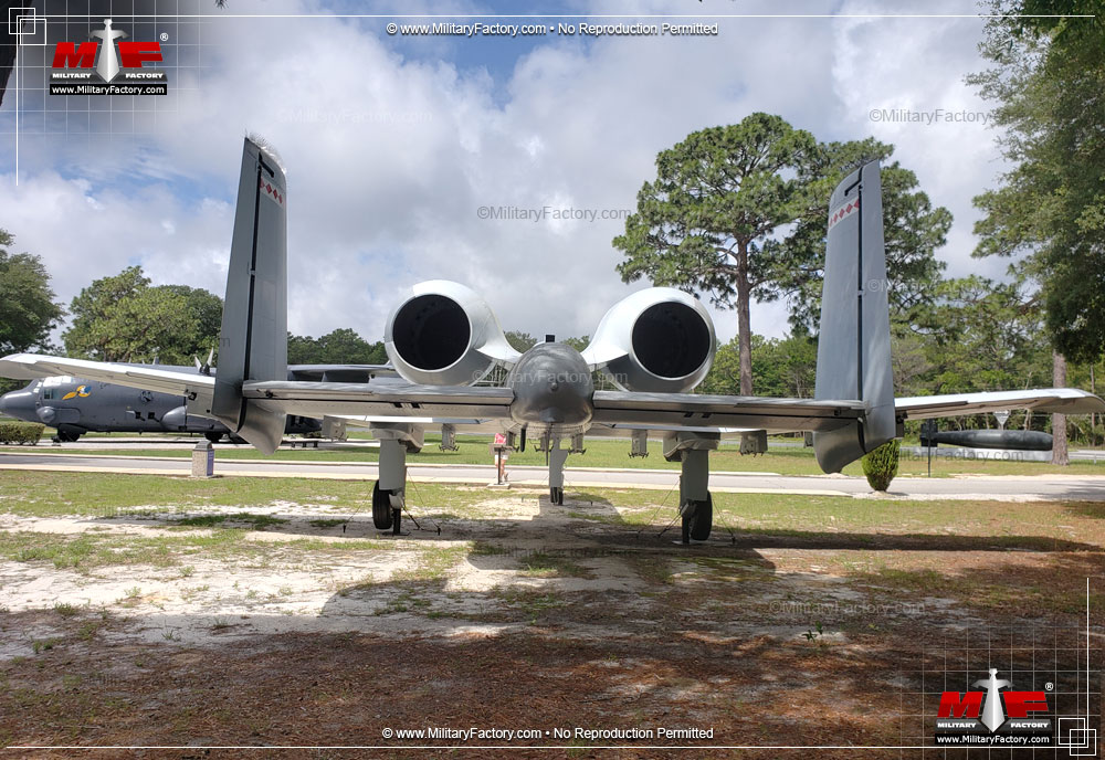
Power was derived from a pair of high-mounted General Electric TF34-GE-100 series turbofans. These are rated to just 9,065lb of thrust each and kept the A-10 a subsonic performer incapable of supersonic flight. However, for the CAS role, supersonic speed was a non-essential component. In fact, the A-10 came in over 2,000lbs heavier than initially intended. The added weight was simply written off by the USAF, believing the slight decrease in speed was manageable in the CAS role. The engines were mounted high to keep them as far away from ground fire as possible while also keeping them clear of ingesting foreign objects when operating from unprepared airfields. The A-10 can operate with one complete engine being lost to action. Each engine nacelle was angled up ever so slightly to 9 degrees to bring the combined thrust outflow more in line with the airframe's center of gravity. The all-important Auxiliary Power Unit (APU) was fitted in the fuselage near the engines, its exhaust port always marking the portside engine nacelle with a streak of black soot.
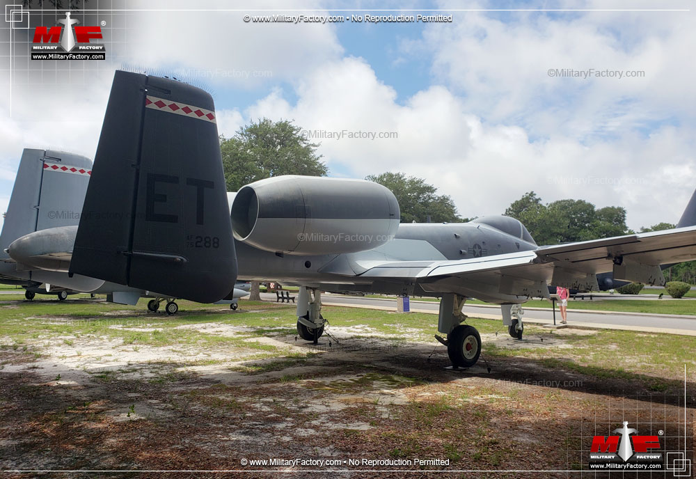
The Empennage
The empennage was dominated by the twin vertical fin tail design, each fin holding its own rudder control. The horizontal tailplane was set low on the fuselage and fitted the vertical fins as outward from centerline as possible. Each tailfin sported slight sweep along the leading edge and no sweep along the trailing edge. The fins sat high above the stabilizer, the stabilizer itself also working to reduce the amount of visible heat exhaust being generated by each turbofan engine. This helped to make tracking and lock-on by ground-based radar somewhat tougher.
A-10 Performance
Listed performance for the A-10A included a top speed of 439 miles per hour with a cruise speed of 340 miles per hour and a never-exceed speed of 518 miles per hour. Stall speed was 138 miles per hour. Combat radius was nearly 300 miles depending on payload and mission type. Ferry range was a reported 2,580 miles. Service ceiling was 45,000 feet with a rate-of-climb equal to 6,000 feet per minute.
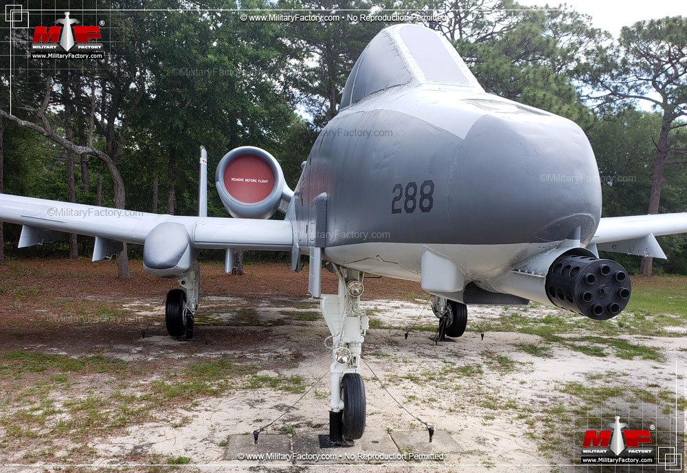
The GAU-8/A 30mm Cannon
The GAU-8/A was the heart and soul of the A-10 Thunderbolt weapon system. This massive 679-pound seven-barrel rotating cannon operated on the relatively simple Gatling principle made popular by American inventor Richard J. Gatling in the time of the American Civil War. The general principle held that a set of rotating barrels could cool themselves faster during the firing action. This allowed for an exceedingly high rate-of-fire without the overheating problems common to a single barrel repeating weapon. General Electric designed and developed the GAU-8/A "Avenger" system used in the A-10 Thunderbolt II, an armament from which the A-10 was essentially built around. In true A-10 speak, the GAU-8/A is actually part of the 4,200lb A/A49E-6 weapons system when detailed as a collective unit.
Some interesting notes compliment the GAU-8/A. Its seven-barrel function means that the entire barrel system is slightly offset to the left to keep the firing barrel aligned with the fuselage centerline. The weapon system, as a whole, is also quite large (including the ammunition drum). The size is such that a picture was released during development showing the GAU-8/A dwarfing the overall size of a Volkswagen Beetle. In fact, the GAU-8/A is closer to the size of a full-size family sedan when measured end to end. The photograph quickly made the runs of various magazines and helped to promote the intimidating aura of the Avenger system.
Operation of the GAU-8/A is controlled via a gearbox with two separately-controlled hydraulic drive motors. The weapon sits under the cockpit floor and shares space with the nose landing gear. The main barrel assembly runs from under the titanium tub and protrudes just passed the curved nose assembly. The barrels are attached to a transfer unit which is backed by a hydraulic drive system. The whole unit is connected to the all-important ammunition drum which sits on its long side behind the cockpit. A double-layer conveyor belt system feeds fresh 30mm projectiles to the barrels while removing spent shell casings in return. Spent shell casings are not jettisoned from the A-10 upon firing, as is common with most other military aircraft, reducing the chance that any spent casings will be ingested into the engines. Exhaust ports for the GAU-8/A are located along the underside and sides of the forward fuselage. A gun nozzle seal protects the protruding section of barrels at the front. The ammunition loading door is under and aft of the cockpit along the underside of the fuselage. A fresh ammunition drum can be installed by trained technicians in as little as thirteen minutes. The drum system is attended to by a specialized four-wheeled ammunition loading assembly cart - the Syn-Tech GFU-7/E - the only specialized piece of equipment that the A-10 needs at a forward operating base. An ammunition drum is typically fielded with 1,174 rounds of 30mm projectiles.
The A-10 GAU-8/A cannon utilizes large 30mm projectiles in three major forms, each full projectile measuring in at an impressive 11.4 inches in length. The projectile is primarily made up of the cartridge case, this making up roughly half of the projectiles length, with a tapered upper portion ultimately concluding in the pointed nose cap. Available projectile types include the PGU-13/B High-Explosive Incendiary (HEI), the PGU-14/B Armor-Piercing Incendiary (API) and the PGU-15/B Target Practice (TP) rounds. Typically, ammunition is loaded in what is known as a "Combat Mix" - an HEI round followed by five API rounds. The HEI round doubles as an aiming tracer round for the pilot. The TP round, though technically a trainer projectile, can also be used against lightly skinned vehicles and forms the least expensive munition for the 30mm cannon. The API weighs in at 1.6lbs while the HEI and TP rounds are both 1.47lbs.
The API round is a depleted uranium projectile and is proven to penetrate any modern battlefield tank in operation, even those further protected by "reactive armor" panels. The HEI round is adept at killing lightly-armored vehicles by its deadly fragmentation "spray" and can also trigger fires some feet away from the target zone itself. While disabling a vehicle, the HEI round is capable of further maiming or killing the occupants. The use of depleted uranium has long held some controversy with watch-dog groups, citing the after-effects the material may have on civilian health.
The GAU-8/A is afforded two rates of fire that allow for settings of approximately 2,100 or 4,200 rounds per minute. Aiming of the gun is through a reticle in the HUD with each barrel sighted and aligned by grounds crew prior to firing. Firing is generally in few second intervals so the rate-of-fire is more accurately reported between 30 and 70 rounds per minute. The gun computer calculates ballistics based on the ammunition type selected by the operator. When fired, the 30mm cannon produces a noticeable cloud of gas that screens some of the forward portion of the fuselage for a brief moment. The velocity of each 30mm round is such that there is little projectile drift once it leaves the barrel and the A-10 aircraft actually slows a few knots of speed in the firing action. The GAU-8/A can be used on slow, low-flying aircraft such as helicopters and was credited with two such kills in Operation Desert Storm. The ammunition for the gun is counted through a conventional counter on the cockpit instrument panel, decrementing the count by a value of ten.
Testing of the gun, as mated to the actual A-10 airframe, began in September of 1974. Though the results of the ammunition on test battlefield tanks proved excellent, it was found that an inordinate amount of dangerous explosive gasses was generated in the firing action, resulting in an external fireball being created ahead of the pilot. The projectile propellant was changed but this resulted in the loss of one of a preproduction aircraft to a flameout as residue from the propellant was now being ingested into the engines. Enter the Battelle device...
The Battelle Device
The Battelle device was developed by Battelle Laboratories as a gas diverter to be fitted to the barrel muzzles of the GAU-8/A. It was a relatively cheap fix but it was soon found to contribute to unacceptable stress fractures of the airframe along various locations of the forward fuselage. As such, the Battelle device was dropped from consideration. Instead, the engines were fitted with a system that maintained continuous ignition for every moment that the 30mm gun was to be fired and for a short time after the trigger was depressed. Additionally, maintenance requirements now stipulated that engines were to be washed once for every 1,000 rounds fired. In effect, the ingestion of the main gun residue into each engine was never fully solved for the life of the A-10 Thunderbolt II, a threat that the modern A-10 pilot faces even today. As an aside, the GAU-8/As rate-of-fire was temporarily revised to 3,900 rounds per minute in preparation for the Battelle device.
A-10 Munitions
The A-10 makes stellar use of the eleven hardpoints allotted to its layout. One is located along the fuselage centerline with two more held to either side of the fuselage undersides. There is another hardpoint inboard of each main landing gear sponson and three more are fitted outboard. Hardpoints are numbered from 1 to 11 when viewing the aircraft in the forward profile (right wingtip to left wingtip). The weapon release sequence - that is, the sequence in which each pylon drops its payload - is as follows: 8, 4, 11, 1, 10, 2, 9, 3, 7 and 5. Hardpoint number six is always reserved for specialized pods (a 600-gallon fuel tank or a pilot's travel pod) and is not wired to drop ordnance. Note that the sequence essentially begins inside of the wheel sponsons, then jumps to an outward-to-inward fashion along the wings, and concludes with the underside fuselage pylons. Also note that each respective pylon also drops their munitions in a certain order all their own so the aforementioned sequence can vary with a full weapons payload (i.e. triple Maverick mountings for instance). This maintains a healthy weight load across the airframe as the ordnance load itself changes.
Some general pylon notes include munition-loading restrictions along hardpoints 1 and 11 as well as 5 and 7. No munitions may be carried on 5 and 7 while 1 and 11 are limited by way of only using drop munitions (no forward firing missiles allowed). Hardpoints 4 and 8 are "plumbed" to accept 600-gallon fuel tanks. The fuel tanks are the same as those used by the General Dynamics F-111 Aardvark swing-wing bomber but most A-10 pictures rarely showcase the extra fuel load. An outboard hardpoint is also generally reserved for the carrying of jammer pods in modern A-10 functions.
The AGM-65 Maverick Air-to-Ground Missile
The A-10 Thunderbolt II is cleared to carry and launch a variety of ordnance including guided surface-to-surface missiles, air-to-air missiles, laser-guided bombs and dumb bombs of conventional origins. Aside from the 30mm cannon, the AGM-65 remains the Thunderbolt's tank-killing system. This family of missiles is proven and comes in a variety of warhead and seeker types. There are six primary forms designated as the AGM-65A, AGM-65B, AGM-65D, AGM-65F, AGM-65G and the AGM-65E. The AGM-65A and AGM-65B are TV-guided missiles fitted with shaped-charge, 125lb warheads. They are differentiated by the B-model's magnified scene, increasing its target acquisition range. Both are fire-and-forget systems with proven performance in daytime actions.
The AGM-65D, F- and G-Mavericks feature infra-red guidance systems - imaging IR with a digital tracker. The D-model shares the warheads of the A- and B-models. The F- and G-models use a 300lb kinetic energy penetrator warhead. The D-model enjoys a day/night attack capability while the F- and G-models are cleared for use against surface ships, a task generally reserved for dedicated anti-ship missile systems such as the Harpoon series.
The AGM-65E Maverick is a laser-guided munition with a 300lb kinetic energy penetrator warhead. Guidance is passive laser with a digital tracker but can tackle laser-designated targets in both day and night actions.
Launch and Drop Munitions
Aside from the Maverick, A-10 pilots enjoy a healthy stable of conventional launch and drop munitions. The former is made up of traditional LAU-10 series rocket pods for use against structures and soft-skinned targets. Rocket pods are carried on stations 3 and 9. The latter comes in the shape of the family of drop bombs (also called "dumb" bombs). These are formed by the 500lb Mk 82 and the larger 2,000lb Mk 84 bombs. When fitted with retarding glide fins, these bombs are known as the Mk 82SE and Mk 84SE "Snakeye" bombs. The A-10 is also cleared to drop laser-guided bombs though, unlike other aircraft in the US inventory, the early Thunderbolts could not "self-designate" - that is, mark her own targets and launch their guided bombs. She instead relied on friendly ground personnel to "laze" a target for her before launching. Standard laser-guided bombs for the A-10 include the GBU-12 500lb bomb and the GBU-10 2,000lb bomb. Regardless of the "laser-guided" designation, these are nothing more than slightly modified forms of their dumb cousins, made more lethal by their guided accuracy by way of field modification kits. So long as the laser designator stays trained on the target, the guided bomb will follow its flight path along the reflected energy generated by the ground laser to the relative target location.
Other weapons included the Mk 77 incendiary bomb, the BLU and CBU series cluster bombs, Paveway LGBs, Joint Direct Attack Munitions and Wind Corrected Munitions Dispensers. Targeting pods for the A-10 now include the LITENING system (specifically the A-10C) and allow the A-10 to "self-designate" its missile and laser-guided targets without requiring ground forces to do it.
Self-Defense
Aside from her design and armoring, the A-10 Warthog stays alive through a series of built-in functions. Perhaps most important is use of an Electronic CounterMeasures (ECM) pod - most likely the ALQ-131 ECM pod (also the AN/ALQ-184 ECM). The pod is usually fitted on an outboard wing pylon. These pods serve to jam incoming enemy radar transmissions and attempt to deflect lock-on by ground based radar installations and systems. In addition to the ECM pod, A-10s make use of conventional chaff (interference foil strips) and flare (deflective heat source) launchers to counter the tracking of ground-based missiles that have been launched. These dispensers are mounted at the wing tips as well as just behind each wheel sponson. The SUU-42A/A flares/Infrared decoy and chaff dispenser pod is also optional.
The AIM-9 Sidewinder forms the other portion of the Thunderbolt II self-defense toolbox. These missile systems are essentially as those found on other American fighter aircraft and provide a healthy and lethal defense against enemy helicopters and other aircraft. The AIM-9 is a short-ranged weapon and only two are generally ever carried on the A-10, usually on the wing opposite the pylon holding the ECM pod, though an additional pair can be mounted in the opposite placement in place of the ECM pod itself. One Sidewinder can be carried on the standard A-10 pylon though the LAU-114 launcher rail allows for a pair to be affixed and launched as normal.
The 'Hawg in Europe
Warthog crews and their mounts were stationed in Europe, the site of what was to become the battlefield for which the system was always groomed for, and became a part of the USAF's largest combat wing there. The Thunderbolt maintained a healthy operational range and could reach places within East Germany and some layers beyond when called to action. There were four major Forward Operating Locations (FOLs) and six in total. The four were located at Ahlhorn, Noervenich, Sembach and Leipheim in West Germany. A-10 pilots could easily have been called to action to help defend far-off places like Italy and Norway if need be as well. Pilots cycled in and out of service within this region to learn the layout of the land, get exposure to flying in the regional elements and commit to memory the battleplan should a Soviet ground assault ensue. As the initial wave of Soviet strikes would most likely target airfields, the A-10 was also tested on highways and unprepared positions to fully "stretch" her legs. Some 72 A-10 Thunderbolt IIs could be made available in the event of a Soviet invasion.
The A-10 would have worked in conjunction with the US Army's AH-64 Apache in the anti-tank role, assaulting Soviet armored columns as they made their way to key objectives. With the end of the Cold War, many A-10 Thunderbolts were brought back state side with talks of retiring the old girl. Only the 52nd FW based out of Spangdahlem Air Base in Germany was to remain.
A-10As in Europe were painted over in a European woodland camouflage scheme using a combination of greens and dark grays, the thought being they would mesh well with the surrounding terrain.
Warthogs in Desert Storm
Despite its appearance in the 1970s, Thunderbolt II pilots had to wait sometime before being able to prove their machine in actual combat. That came along in the form of the 1991 Gulf War - through Operation Desert Storm - versus Saddam Hussein's "4th largest army" in the world. Hussein moved his ground forces from Iraq into Kuwait in an attempt to capture a large portion of the regions oil production. A United Nations effort ousted his army back onto Iraq soil in the first true "digital" war, a war that brought about the first combat actions for the M1 Abrams and the F-117 Stealth Fighter. By the end of it all, Hussein's army was reduced to a rabble of retreating (or surrendering) personnel with little in the way of discipline. This was due, in some part, to the actions of the A-10 and her crews.
Some 144 A-10A and OA-10A aircraft were sent to the region from the 23rd TFW(Provisional) and 354th TFW(Provisional) making up five squadrons operating out of King Fahd International Airport in Northeast Saudi Arabia (74th TFS formed the dedicated night wing). The first recorded combat missions by an A-10 occurred on January 15th, 1991. Targets included all sorts of manner made up of trucks, tanks, armored personnel carriers, vehicles, bunkers, radar installations, artillery emplacements, missile batteries and grounded aircraft. In the end, the A-10 accounted for over 15% of all coalition sorties, totaling 8,755 all their own. Tanks proved the major target and no Soviet-made armor in Iraqi hands was safe from the smiling, sharp-toothed Warthogs, essentially making "aces" out of her pilots (though these kills achieved against tanks, and thusly not "proper" aces).
The A-10 proved exceptional in her role. She showcased the long loitering times she was required to have and her armament delivery capabilities were second to none. 'Hogs were able to deliver their payload against multiple targets, return to friendly forward bases and reload, only to head out and deliver their payload once more. Her durability and ease-of-maintenance was also worth noting. Many-a-report recalled whole sections of fuselage or wing surface area being peppered with enemy flak with the A-10 pilot returning safely home. Moreso, large sections of wing and tail surfaces could be lost and still keep the aircraft fly-worthy. In all, the A-10 accounted for the destruction of 987 Iraqi tanks and 500 APCs. 926 artillery systems and 1,106 trucks also fell victim to the might of the Warthog.
In addition to traditional sortie runs against vehicles, the A-10 was called upon to support special operations forces on the ground in the Close-Air Support role. She was also given instruction to utilize her loitering capabilities in the location and possible destruction of SCUD missile sites when available. Other non-conventional targets soon were brought into the HUD of the A-10 and included supply depots and arm stores. The beauty of the A-10 was that she could assault all of these targets by cannon, bomb or missile as needed.
All was not rosy for the A-10 crews however. Their mission set included some of the most dangerous low-level runs imaginable where hostile AAA (Anti-Aircraft Artillery) could quickly open up and spear the internal workings of the 'Hog. Regardless of such damage, an A-10 could be repaired and back in the air in a matter of days. Nearly half of the 144 fielded Thunderbolt's would receive some level of damage during the war. Six Thunderbolts were lost to enemy SAMs (Surface-to-Air Missile) systems while a further 14 were damaged.
In all, the Persian Gulf War served as a suitable test ground to usher in the weapons of tomorrow. Saddam Hussein maintained a large land army at the time, though much of his equipment was adequate at best and his men's training below average for the most part. The result was a lopsided coalition victory that showcased the strengths and weaknesses of the respective armies at play and brought about changes to both technology and doctrine in the years following. The A-10, once on the cusp of her twilight years, had proven her mettle and made a bona fide star of the ugly aircraft with her unique brand of pilots.
Perhaps worth noting is that the A-10 was credited with two air kills during the war, both at the hands of the GAU-8/A cannon and against a BO-105 and Mil Mi-8 helicopter in different instances on February 6th and February 15th, 1991 respectively (different pilots as well). It is interesting that the AIM-9 Sidewinder did not record a kill in the whole of the war with just three being fired on accident. Thunderbolts deployed to the Persian Gulf were also sans any night attack capability. Pilots flying at night generally relied on the FLIR of their AGM-65D IIR Maverick systems for the task - this method not endorsed by the USAF.
The Two-Seat Night-Attack Warthog
Though developed but never produced, there did exist a two-seat dedicated night attack version of the A-10A. The two-seater was designated in the developmental YA-10B fashion and would have gone on to become the "A-10B" in production. Using a production A-10A as the conversion model, a second seat was added in tandem fashion, affording the rear crewmember a view over the pilots seatback. The cockpit was redundant for the most part, mimicking the controls of the forward position and the only component differentiating the two was the lack of a HUDs element in the rear position. Each cockpit was given a curved canopy that opened to the starboard side with a "A" frame separating the two assemblies - this would have become a rear-hinged unit in production models. The 30mm nose cannon was retained. To offset the added weight and position of the second cockpit in relation to airflow and stability, the vertical tail fins were heightened by 20 inches each (later shortened by 12-inches). The YA-10B was fitted with two distinct recce pods, the AAR-42 FLIR and the WX-50 ground-mapping radar. The former was fitted to the starboard side fuselage hardpoint and the latter to the port side fuselage hardpoint. Other specialized components were fitted and still others were tested for possible use. All of these additions increased the base A-10A airframe some 2,000lbs. Interestingly, the important titanium tub armor protection was not extended to the rear crewmember, this despite the decided weight gain of the new design.
Republic put up some of the development money and the rest was handled by the USAF. Low priority to the project meant that the aircraft lingered in development for some time. Republic attempted to market the two-seat A-10B as not only a dedicated night-strike platform but also a combat-capable two-seat trainer conversion model. Additionally, the A-10B could be used in the air defense suppression role thanks to its payload capabilities and loiter times. Another effort marketed the new A-10B as an anti-ship maritime strike aircraft. Alas, the A-10B never materialized beyond the single YA-10B prototype. The USAF rebuffed the new design, as did interested foreign parties, and the sole YA-10 was handed over to the Air Force Flight Test Center Museum at Edwards AFB in California.
Training for A-10 pilots was handled simply by having an instructor in another A-10A accompanying the primary student A-10A pilot for his/her first few flights.
The OA-10A
The Base A-10A was modified in 1987 to create the airborne Forward Air Control (FAC) observation platform in the OA-10A. The USAF was desiring additional F-15 Eagle and F-16 Fighting Falcons in their Cold War stable and developed a scheme to acquire them by labeling the A-10A as passed their prime, assigning them to the inglorious role of Forward Air Control (FAC) under the designation of "OA-10A". Modified F-16 Fighting Falcons would now take the place of the A-10A in the CAS role. Essentially, the OA-10A differed in no way from the attack A-10A except in mission specification. The OA-10A eventually replaced the highly-effective but aged Rockwell OV-10 Broncos in the FAC role. Despite the designation, the OA-10A remains a fully combat-capable airframe. In October of 1987, the 602nd Air Control Wing out of Davis-Monthan AFB began taking delivery of the OA-10A. Creation of the OA-10A also brought about two new Air National Guard groups in 1990 and 1991, these becoming the 110th TFS out of Michigan and the 11th TFS out of Pennsylvania.
Upgrading the Hawg
The A-10 received some much needed attention in the 1980s. The system was heading towards a mid-life crisis and the LASTE (Low-Altitude Safety and Targeting Enhancement) program was put into effect. This program would substantially upgrade the core avionics package of the A-10 with ground collision, an F-16 style computerized weapons delivery system, revised HUD for air-to-air work, improved software support and (finally) the addition of an autopilot system. The program, though developed and cleared, did not go into effect until after the 1991 Persian Gulf War. Later improvements also allowed use of night vision goggles by the pilot, no longer counteracted by the light emitted from the A-10 instrument panel at night. Night vision upgrades were completed in 1997. New INS and GPS compatibility occurred in the 1990s as well.
Blasphemy: The Warthog in Foreign Hands
The Thunderbolt was not always going to be an American only product. It was almost inevitable that an ally would come calling for such a potent tank-killing system and Turkey nearly became a major operator of the time (Israel, Egypt and South Korea were also contenders). In 1993, Turkey shown interest in obtaining fifty examples while American warplanners were beginning to move away from the A-10. However, the US State Department intervened and killed the deal altogether, citing an objection to exporting the depleted uranium projectiles needed in the GAU-8/A cannon. Cost escalations on Turkey's side also left the deal in limbo and the sale was never finalized.
The Here and Now: The A-10C
Lockheed Martin now sustains the A-10 Thunderbolt II and supports software and other upgrades. Some 356 A-10 and OA-10 Thunderbolt IIs are scheduled or modernization through the incremental A-10 Precision Engagement Modification Program. The cockpit will feature some F-16 styling with two 5.5-inch color displays, a moving map display and a digital stores management system. The changes have therefore created a new variant within the A-10 family known under the designation of "A-10C". A-10Cs have already been deployed to Iraq in 2007 as part of the 104th Fighter Squadron, ANG out of Maryland. Many operational A-10 squadrons run a mish-mash of A-10A strike and OA-10A observation models, covering a mix of battlefield sorties should the need arise including that of Search & Rescue (SAR) of fallen comrades, FAC and CAS.
As of this writing, the USAF intends on keeping its fleet of A-10 Thunderbolts optimistically flying up to 2028 with potential replacement coming in the form of the highly-advanced Lockheed F-35 Lightning II. A-10s have also been featured in the War in Afghanistan, responding in the CAS role as needed. To date, some twenty A-10 squadrons exist with the USAF, ANG and the AFRC. Seven hundred fifteen total Thunderbolt IIs were eventually delivered at a unit cost of $11.7 million dollars apiece. Two were YA-10 prototypes while six became YA-10A preproduction evaluation aircraft. The rest were production A-10A and conversion OA-10A and A-10C models.
After the end of the Cold War (and post-Desert Storm), the European camouflage of the A-10A gave wave to a more subtle and generic dark-gray-on-light-gray paint scheme. Sometimes false canopies are painted along her underside to confuse enemy ground parties. Nose art, though not officially accepted by the USAF, was utilized to good effect in the Gulf War by A-10 crews.
The phrase "Go Ugly Early" is a motto associated with the A-10 Warthog and is generally a call by ground troops requiring the lethal force of the A-10 early in a battle.
As it stands in early 2014, the A-10 remains a candidate for formal retirement due to changing conditions in the global American commitment and costs for maintaining and modernizing the fleet. The move remains controversial and many efforts have arisen to ensure the fleet remains active into 2030. Some commanders believe the same role is handled effectively by F-15s, F-16s, AH-64 Apache gunships and Unmanned Combat Air Vehicles (UCAVs).
In early 2016, it was announced that the A-10 Thunderbolt II fleet was to be kept alive in the DoD budget heading into 2017.
February 2017 - It was announced that the A-10 Thunderbolt II series will continue in frontline service up until 2021 for the USAF after which point its status in the active fleet will be reassessed.
April 2018 - The USAF is moving ahead with "rewinging" a stock of about 110 A-10 aircraft to help extend their service lives. These will join the 170 or so that have already received the new appendages from Boeing.
Operators Global customers who have evaluated and/or operated the Fairchild Republic A-10 Thunderbolt II (Warthog). Nations are displayed by flag, each linked to their respective national aircraft listing.
Total Production: 713 Units Contractor(s): Fairchild Republic Aviation - USA
[ United States ]
1 / 10
Image copyright www.MilitaryFactory.com; No Reproduction Permitted.
2 / 10
Image copyright www.MilitaryFactory.com; No Reproduction Permitted.
3 / 10
Image copyright www.MilitaryFactory.com; No Reproduction Permitted.
4 / 10
Image copyright www.MilitaryFactory.com; No Reproduction Permitted.
5 / 10
Image copyright www.MilitaryFactory.com; No Reproduction Permitted.
6 / 10
Image copyright www.MilitaryFactory.com; No Reproduction Permitted.
7 / 10
Image copyright www.MilitaryFactory.com; No Reproduction Permitted.
8 / 10
Image copyright www.MilitaryFactory.com; No Reproduction Permitted.
9 / 10
Image copyright www.MilitaryFactory.com; No Reproduction Permitted.
10 / 10
Image copyright www.MilitaryFactory.com; No Reproduction Permitted.
Similar Developments of similar form-and-function, or related, to the Fairchild Republic A-10 Thunderbolt II (Warthog) Close Air Support (CAS) / Forward Air Control (FAC) Specifications and Pictures.
Going Further... The Fairchild Republic A-10 Thunderbolt II (Warthog) Close Air Support (CAS) / Forward Air Control (FAC) appears in the following collections:
The "Military Factory" name and MilitaryFactory.com logo are registered ® U.S. trademarks protected by all applicable domestic and international intellectual property laws. All written content, illustrations, and photography are unique to this website (unless where indicated) and not for reuse/reproduction in any form. Material presented throughout this website is for historical and entertainment value only and should not to be construed as usable for hardware restoration, maintenance, or general operation. We do not sell any of the items showcased on this site. Please direct all other inquiries to militaryfactory AT gmail.com. No A.I. was used in the generation of this content.